 use case specification" width="800" height="600" />
use case specification" width="800" height="600" />
This article provides use case specification guidance gained from working on many projects across a number of different organisations and industry. It will help those seeking to understand how to write use case specification and understand what is described in use case specification. So what is a use case specification? A use case specification captures the requirements, typically of a system, in the form of a use case that contains the descriptive requirements steps in a logical sequence so that document specification can be understood by users to obtain sign-off of their requirements and for testers and developers to understand what is needed by the system to test and build the system functionality detailed in the system use use case. Use cases and use case specifications were popular in the unified modelling language (UML) and is still used in some corporate environments. Having a good working knowledge of use cases and how they structured provides a very good basis for understanding and transitioning to using user stories in agile ways or working. As a use case can be split into another user stories. The article answers a number of the questions that business analyst ask who are new to use cases and seeking detailed guidance. The article will also help business analyst on how to write use case specification and understand sections of a use case specification template. The article also provides use case specification examples section extracts and use case textual description examples so that you can review and a get a good feel of what to specify in an use case specification document. The article also provides guidance on writing and formatting use case business rules examples in business analysis. Some readers may be interested in a recommended use case training course .
Initially, during the early inception, actors and use cases will be identified, associated, named, given a brief description and an intuitive view of the size/complexity of the use case will be determined. The reasons for doing this are to:

During the Inception Phase, the use cases will be further described to an outline level of detail, this is important in order to:
By the end of the inception phase, all of the use cases should have been described to an outline level of detail. The “outline” level use-case specification should include the following sections (see later sections in this document for descriptions of the various use-case specification sections):
In addition to the above, if any of the other details (business rules, special requirements, issues) have been captured whilst capturing the “outline” level of detail, these should be included within the “outline” use-case specification.
Note: It is recognised that in a large proportion of use cases, the alternative flows usually contain a great deal of the complexity involved within the use case. Therefore, when an alternative flow is considered to be significant (i.e. it contains some complexity or may involve many steps) it should be described in more detail to ensure that the complexity of the flow is understood as is therefore not under or over estimated.
Ideally, this description should take the form of the outline steps involved, however, a paragraph describing the functionality of the alternative flow will suffice if this is not possible.
Once the “outline” use case has been agreed, the use case will then be elaborated to the full specification, the full specification should include all sections completed. By the end of the elaboration phase, approximately 80% of the use cases should have been described to a fully detailed level.

The following sections describe the contents of the various sections of the standard use case specification.
This use case specification section should be populated with the relevant use-case diagram(s). To avoid inclusion of large use case diagrams, a separate use case diagram should be produced for the use case being described, this diagram should detail the use case and any interacting actors and associated use cases. This is referred to as the “use case perspective” use case diagram.
The brief description of the use case specification section should be populated with the brief description of the use case documented. This description should give an overview of the purpose and scope of the use case and clearly define the end goals of the use case. A single paragraph will usually suffice for this description, however, for more complex use cases, a number of paragraphs may be required.
Note: A single sentence that does not give much more information than the use case name is not acceptable.
To aid in the understanding of the use case, it may be appropriate to include supporting diagrams into the use case specification, the most common would be:
The inclusion of these diagrams is optional and should only be done when it aids to the understanding of the use case.
This use case specification section should describe the pre-conditions relevant to the use case. A pre-condition of a use case is the state that the system must be in prior to the use case being initiated in order to ensure that the actor will achieve their goal. The pre-conditions may reference other use cases that must have been successfully executed or may be a textual description of an event that is not represented by a particular use case.
Note: Each pre-condition will have a separate sub-section within the use case specification.
This use case specification section should describe the post-conditions relevant to the use case. A post-condition of a use case defines the state the system must be in immediately after a use case has finished. The post-conditions may be a textual description of an event or description of information being passed to another use case e.g. The business will now have been transferred and the user manually produces a letter of confirmation to the IFA which may include the Unearned Commission Liability report.
Note: Each post-condition will have a separate sub-section within the use case specification.
The flow of events in the use case specification section provides the main bulk of the use case specification and describes what the actor does and what the system does in response. It is phrased in the form of a dialog between the actor and the system. The use case describes what happens inside the system, but not how or why.
The glossary should also be used to maintain the definitions of all business terms used in flow descriptions, this ensures that each term has one agreed definition across all use cases and also helps simplify the use case descriptions.
Do not describe specific design items such as user interface screens or controls into the description. Instead, describe these in the Use case storyboard.
Trigger
This use case starts when the actor does something to trigger it – an actor always initiates use cases. The trigger should be documented as the first step within the use case flow of events e.g. 1. This use case starts when the user….
Steps
Each step should be described using standard use case vocabulary (requests, sends, asks, where) and sentence style e.g.
For what the actor does
‘The User requests the to …’
For what the system does in response
‘The System sends message to and …’.
For business rule checks
Within the flow of events, the name of the actor will not be referenced as this is clearly displayed on the use-case diagram, instead ‘The User’ will be referenced. However, if it is not appropriate for the use case flow of events to reference ‘The User’ (i.e. when the Actor is Time or an external system), ‘The Actor’ should be used.
Each step within the flow of events should be numbered sequentially.
Sub-Headings
To aid understanding and navigation within use cases it can often be useful to include headings within the flow of events describing the action of a group of steps. These headings are not required across all use cases, but are most useful within large, complex use case flows involving many steps.
Example
Process Unearned Liability
Transfer the Business
Looping
In certain circumstances, the flow of events may require a number of steps to be repeated until a certain condition is true, in this circumstance, the FOR EACH…..REPEAT statement should be used e.g. FOR EACH Attribute REPEAT Steps 8-12.
IF statements
Simple alternatives may be described within the Basic Flow of the use case to describe unusual optional processing or exception processing. If it only takes a few steps to describe the alternative processing, do it directly within the Basic Flow of Events section (using an IF statement), rather than using an Alternative Flow.
The ‘IF’ statement should be a separately numbered, nested step within the Basic Flow (see Nesting sub-section below). The ‘IF’ statement should be nested below a step expressing the base course of action or summarising the nested steps.
Example
The System validates the Customer information entered, any errors must be resolved before progressing with the use case, any warning messages can be accepted and the use case continues:
IF any of the mandatory fields have not been entered [BR1], the system displays an error message indicating that the mandatory fields that have not been entered (MSG0001)
Nesting
In certain circumstances, a step within the flow may actually have a number of nested steps. This prevents the need for breaking the nested steps into an alternative flow. When describing nested system processing, nested numbering should be used (e.g. 4. 4.1. 4.1.1.).
However, if too many levels of nesting are used within the flow, the use case can become very difficult to understand. Therefore, as a rule, no more than 2 levels of nesting should be used (i.e. 4.1.1. is acceptable, 4.1.1.1. is not acceptable).
Referencing Included Use Cases
If the flow needs to reference an included use case, embed the activation of the included use case in the flow, stating the name and reference number of the use case. The standard language for activating an included Use Case to be used is ‘INVOKE’.
E.g. On selection of the Organisation Element, the System will INVOKE UC11 View Party which will display the details of the selected Organisation Element.
Referencing the User Interface
It is useful to provide a cross-reference between the use case and the use case storyboard to aid understanding of which screens/pages are displayed at particular stages of the use cases. This approach has proven particularly useful for the designers and testers.
This is to be achieved by allocating a unique identifier to each user interface with the use case storyboard. The Unique Identifier of the User Interface should take the form UcnnSCxx. This unique identifier can then be referenced alongside the step in the flow of events where that user interface is first displayed.
E.g. The System prompts the User to enter the Search Criteria (UC10SC01).
Data Items
Where information is exchanged between an Actor and the system, be specific about what is passed back and forth. For example, it is not very illuminating to say that the user enters ‘customer information’. Information about Data Items is also contained in the in the use case storyboard artefact. Use the following guidance with respect to the amount of information to capture in the use case with respect to data exchange.
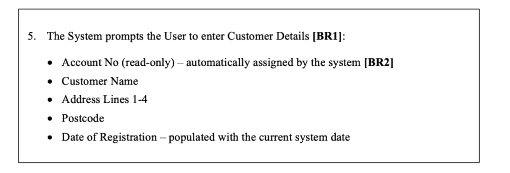
List in detail the data items that are displayed on screen or passed between an Actor and the System, e.g. First Name, Surname, Address Lines 1-4, Post Code, etc.
Alongside each data item in the list, identify whether it is read only/disabled, and any notes applicable to that data item.
Example
A business rule should be used to describe which data items are mandatory. A separate business rule should be used for each separate instance of data exchange between an actor and the system to define the mandatory data elements of that interchange.
Any validation that occurs on a data item (e.g. a date between a particular range) or between data items (e.g. the value of one data item may effect the values allowed for another data item) should also be described as a business rule.
Only identify the available/selectable values for a data item in the flow of events, if the value of the data item is referenced within the use case or if business rules exist in relation to selection of a particular value.
To clarify, the data type, (e.g. numeric, date etc), format (e.g. dd/mm/yyyy) and length should be documented within the use case storyboard.
Error Messages
Where an error or warning message is reported to an actor, the use case flow of events must state where in the flow of events that the message needs to be reported and provide an indication of what the message is about. The precise message text, however, should be stored in a separate artefact, which will be referred to as the Message Catalog.
This artefact is in addition to the standard RUP artefacts. Each message in the Message Catalog should have a unique identifier of the form MSGnnnn, and the use case flow of events should reference this unique identifier, e.g. “The system displays an error informing the user that the product cannot be supplied on the date requested due to the associated lead time (MSG0001)”.
The flow of events should make it clear whether the message is an error (where the user must take a different course of action) or warning (where the processing will continue following user acknowledgement of the message) to the Actor, e.g.
“The system warns the user that delivery on this date cannot be guaranteed (MSG0002)”. The specific text of the errors and warnings should be agreed with the stakeholders and then implemented by the development team during build.
Following the display of an error/warning message, the flow of events should be explicit as to what happens next. To avoid use of looping GOTO statements which can make the flow of events difficult to navigate, it is recommended that a statement is made prior to the validation stating what happens in the event of an error and what happens in the event of a warning (see Example).
There are options available to reduce the amount of duplication of messages by making the messages generic and “parameter driven”. A good example of where this approach works well is for messages notifying the user that mandatory information has not been provided.
To make this message generic and “parameter driven”, in the message text, replace the parameter with the percentage sign (%) followed by a sequential number (unique within the message).
Then in the Parameters column, list the sequential number and the parameter that it relates to. For example, to display “Field Name is a mandatory field – please enter”, the following message would be put into the “Message Text” column in the message catalog “%1 is a mandatory field – please enter” and the “Parameters” column would be “1 – Field Name”.
Be aware that this approach to the creation of messages will not work for all types of messages. It is more important that the messages presented to the actor are meaningful than to attempt to make messages generic in an attempt to avoid duplication and increase the re-use of messages.